稳压二极管组成的基本稳压电路图:
图1电路是一个采用稳压二极管(齐纳二极管)的简单稳压器电路。
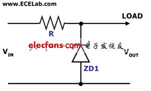
Figure 1. Simple Zener Shunt Stabilizer Circuit Diagram
The circuit in Figure 1 is a simple voltage stabilizer circuit that employs a zener diode and a single resistor. In this circuit, the zener diode, which is the stabilizing component, is in parallel (or in shunt) with the load, which is why it is also called a shunt stabilizing circuit. The value of R must be chosen so that a holding current of 2 mA will flow into the zener diode even at the lowest input voltage and maximum load current. The zener diode maintains the output voltage level by conducTIng the excess current to ground whenever the voltage across it becomes excessive.
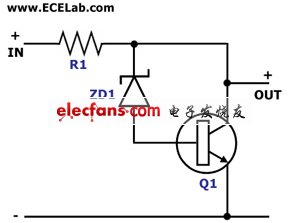
Figure 2. Amplified Zener Shunt Stabilizer Circuit Diagram
The circuit in Figure 2 is another shunt voltage stabilizer circuit that employs an addiTIonal NPN transistor to the simple circuit in Figure 1. In this circuit, the zener diode no longer has to conduct large currents to stabilize the output voltage. The transistor takes care of conducTIng the excess current whenever the current required by the load drops. This circuit is also known as the “amplified zener shunt stabilizer.
。 (本文来源网友上传,如有侵权,可联系管理员删除)
版权声明:网站转载的所有的文章、图片、音频视频文件等资料的版权归版权所有人所有。如果本网所选内容的文章作者及编辑认为其作品不宜公开自由传播,或不应无偿使用,请及时联络我们,采取适当措施,避免给双方造成不必要的经济损失。